Previous lesson: Circuit Python background
Sensors with CircuitPython: Programming the board on Mac OS
Instructions created: 20220216 (i.e., Feb 16, 2022)
- WARNING: Image screenshots and videos are consistent only close to the date this documented was created on, but serve as a general reference.
Learning objectives At the end of this lesson, the learner will be able to:
- Install CircuitPython to a QT Py RP2040 board
- Install a code editor to communicate with your QT Py RP2040 board
- Connect a sensor to your QT Py RP2040 board
- Use pre-constructed code to interact with the microcontroller
Equiptment & Price breakdown 20220403:
- Adafruit QT Py RP2040: 9.95 USD
- Adafruit VCNL4040 Proximity and Lux Sensor - STEMMA QT / Qwiic: 5.95 USD
- STEMMA QT / Qwiic JST SH 4-Pin Cable - 50mm Long: 0.95 USD
Total set-up video time: 571 seconds or 9.51 minutes

Set up CircuitPython
Download CircuitPython
In this step, we’ll install the “operating system” (i.e., CircuitPython) for the board (i.e., QT Py RP2040) into your computer
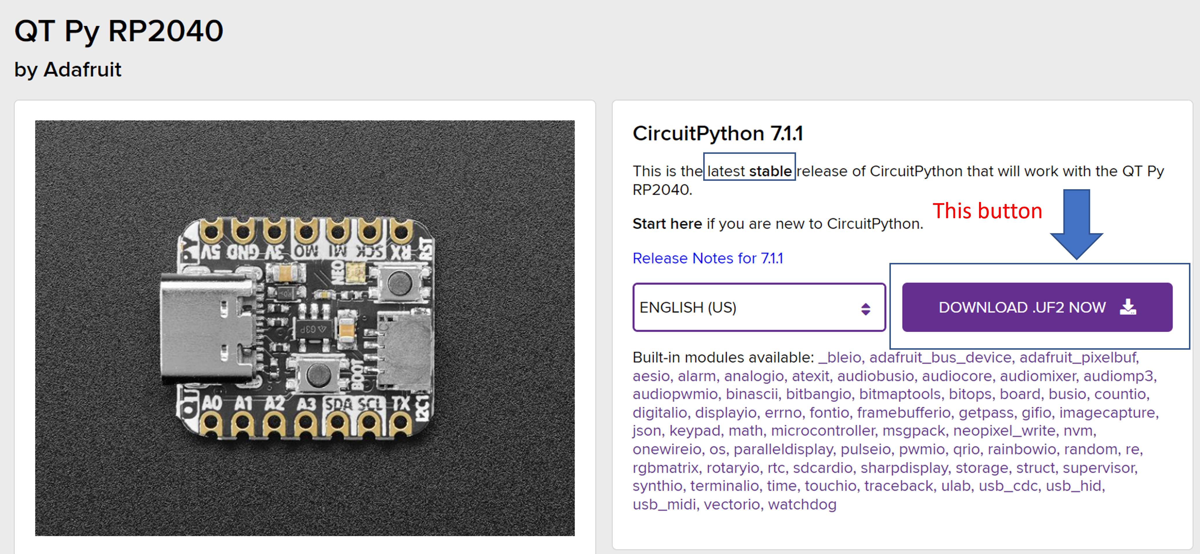
1. Open https://circuitpython.org/board/adafruit_qtpy_rp2040/ link. ALERT: DO NOT open the file after you download it.
2. Download the latest stable release of CircuitPython .UF2 file (i.e., purple “DOWNLOAD .UF2 NOW”) for the QT Py RP2040
3. Save the file in a secure and accessible location in your computer.

Connect the board
In this step, we’ll be connecting the QT Py RP2040 microcontroller board to your computer with a usb cable
1. Connect the type-c end of a USB cable to the QT Py RP2040 board. ALERT: DO NOT connect the board to your computer, yet
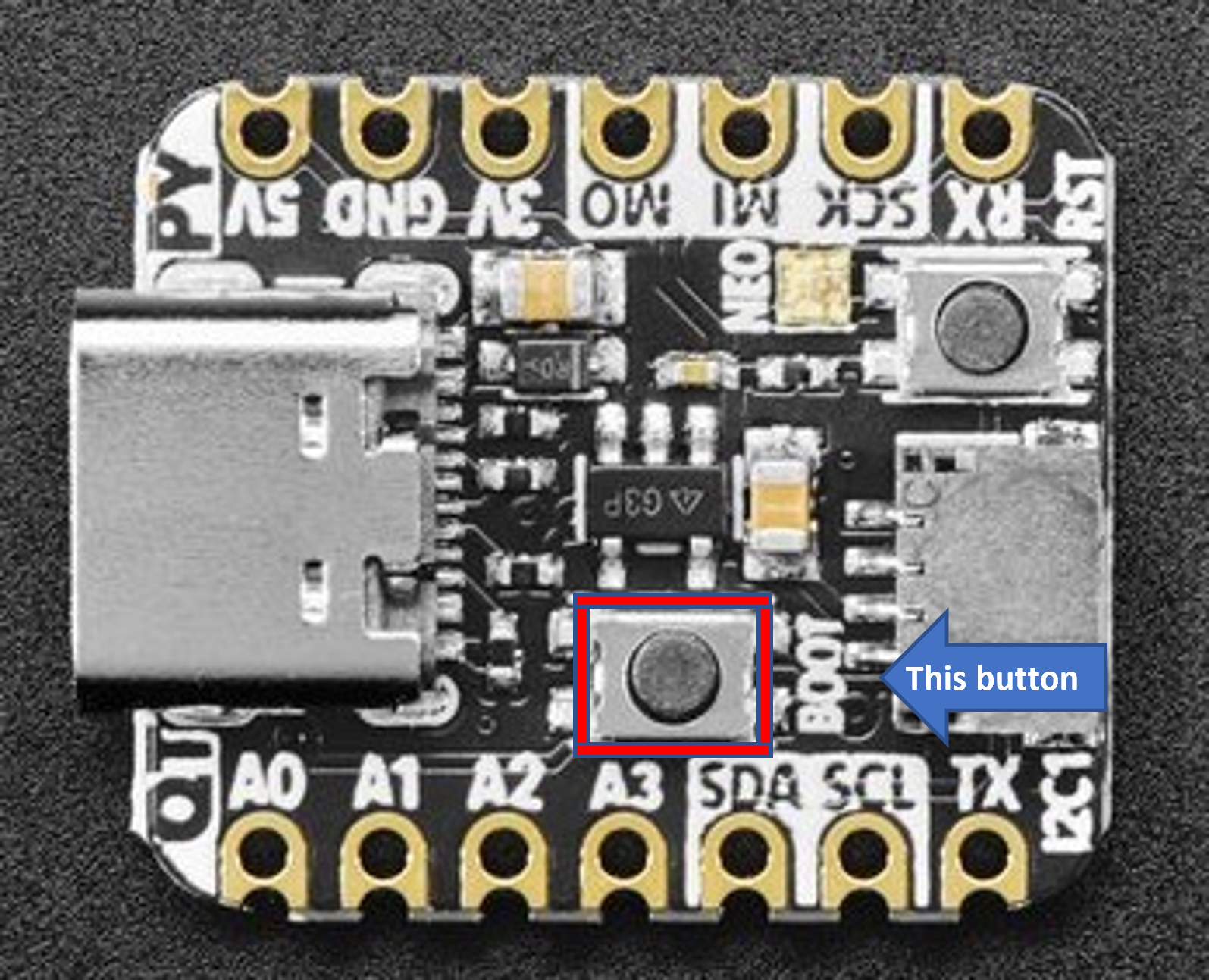
- Below there is a diagram of the QT Py RP2040 board with a red square/border around a button.
- remember where the red “button” is, also known as the boot button.

2. While holding onto the red “button,” located in the center, connect the other end of the usb cable to your computer. After connecting to your computer you can stop holding onto the button.
- Notice: this process is similar to connecting an external drive (e.g., usb drive).
3. To verify if your device recognized the QT Py board, view the “drive” in your finder. It’ll be named “RPI-RP2.”
- Reminder: think of the board as the hardware (i.e., computer) and the .UF2 file as the “operating system” (e.g., Windows 10, OS X, etc.) necessary for the board to run.
Copy CircuitPython to the board
In this step, we’ll be connecting the “operating system” (i.e., .UF2 file) and the board (i.e., QT Py RP2040)
1. Open your finder and locate where the .UF2 file you downloaded in the “Download CircuitPython” step
2. Copy and paste the “operating system” (i.e., .UF2 file) into the external drive (i.e., RPI-RP2) you connected in the “Connect the board” step
- Notice: if you need help finding where they are, ask someone for help
- if done successfully, the external drive is renamed to “CIRCUITPY.”
Install the Mu code editor
In this step, we’ll install a code editor (i.e., Mu editor)
1. Open https://codewith.mu/en/download link
2. Select your operating system (i.e., Windows or Mac OSX) and start to download the Mu Editor in a secure and accessible location in your computer
- Notice: Ask for help if you can’t download Mu Editor. A “Mu Editor isn’t commonly downloaded” warning might appear for some computers. You need to specify that you trust Mu Editor, “keep anyway,” and proceed downloading the editor.
3. Navigate to the location of the Mu Editor in your Finder and proceed to install the Mu Editor, this might take a few minutes (e.g., ~5 min).
- Notice: Mu Editor will attempt to open itself after you install it. The fist launch will take a while to open and begin running. If the editor doesnt open in 5 min, ask for help.
4. Once the Mu Editor launches, or you launch the editor, set the mode to “Circuit Python.”
- if you accidentally picked another mode (i.e., NOT “Circuit Python”), you can reset the mode by clicking the “mode” icon on the top left of the Mu Editor.
Download and install library modules
Download CircuitPython library bundle
In this step, we’ll download circuit python library bundle for version 7.x (i.e., “adafruit-circuitpython-bundle-7.x-mpy-2022XXXX.zip”) into our computer
1. Open https://circuitpython.org/libraries link
2. Scroll down the site to “Bundles” and “Bundles for Version 7.x”
3. Download CircuitPython 7.x (i.e., purple “adafruit-circuitpython-bundle-7.x-mpy-2022XXXX.zip”)
- Save the file in a secure and accessible location in your computer.
4. Navigate to the location of the “CircuitPython-bundle-7.x.x” folder in your device
- Notice:
- Windows: if you are on a Windows device you’ll need to unzip (i.e., “extract all”) the “CircuitPython-bubdle-7.x.x” folder. If you are unfamiliar with “unziping” folder please ask for assistance. We are more than happy to help.
- Mac: Mac users, you don’t need to specify that you want to unzip the folder, your device asks if you want to and then does it for you.
Install modules
In this step, we’ll “install” two Modules from the CircuitPython Library Bundle (i.e., “adafruit_vcnl4040.mpy” and “neopixel.mpy”) into our CIRCUITPY External Drive board. We’ll do that by copying and pasting the two .mpy files from the adafruit-circuitpython-bundle-7.x-mpy-2022XXXX folder into the “lib” sub folder in the CIRCUITPY External Drive.
1. Open the “adafruit-circuitpython-bundle-7.x-mpy-2022XXXX” folder in your Finder
2. Once in the “adafruit-circuitpython-bundle-7.x-mpy-2022XXXX” folder navigate to the “lib” sub-folder within. In there, you’ll find the two .mpy files (i.e., “adafruit_vcnl4040.mpy” and “neopixel.mpy”) and one folder (i.e., ) you’ll need to copy and paste to the CIRCUITPY drive.
- mpy files:
- adafruit_vcnl4040.mpy
- neopixel.mpy
- folder:
- adafruit_register
3. Copy and paste the two .mpy files (i.e., adafruit_vcnl4040.mpy and neopixel.mpy) and the folder (i.e., adafruit_register) from the adafruit-circuitpython-bundle-7.x-mpy-2022XXXX lib sub-folder into the board (i.e., CIRCUITPY (D:)) lib sub-folder
- These files are “modules” (i.e., set of prewritten python code) we will use in this workshop.
- This step is similar to “Copy CircuitPython to the board” Step
Connect a sensor
In this step, we’ll connect a sensor (i.e., Adafruit VCNL 4040) with a with the stemma QT cable (i.e., JST SH 4-Pin Cable 50mm long) to our QT Py RP2040 board
1. Take a stemma QT cable (i.e., JST SH 4-Pin Cable 50mm long) and connect to one end of the sensor (i.e., Adafruit VCNL 4040)
- Notice: The stemma QT cable only fits one direction.
2. Connect the other end of the stemma QT cable to the board
- Notice: if done successfully, the sensor’s light turns on

Exercise:
At this point, you are ready to communicate with the board by loading/writing code scripts (i.e., instructions) into the editor and running/saving the editor
For this workshop we have two preconstructed code for you to copy, paste, and edit in the editor. The goal here is to play with the code, notice the changes, and get a general sense of what is going on with the board and sensor as you edit the code.
The two code blocks we’ll use can be found in this GitHub link
Practice Code for the board
In this exercise, we’ll be using code that is for for the QT Py board. In particular, we’ll be adjusting the LED light by changing the frequency, color, and delay of the QT Py board light.
PHOTOSENSITIVITY WARNING A small percentage of people may experience seizures when exposed to certain lights, patterns or images, even with no history of epilepsy or seizures
1. Within the Mu Editor, press the load button, navigate to the CIRCUITPY drive, and upload the code.py file.
- Notice: this is the file we’ll be working with
2. Copy and Paste the following code into the code.py file into the Mu Editor
import time
import board
import neopixel

pixels = neopixel.NeoPixel(board.NEOPIXEL, 1)

while True:
    pixels.fill((255, 0, 0))
    time.sleep(0.1)
    pixels.fill((0, 0, 0))
    time.sleep(0.1)
3. Press the save button to start running the code
- Notice:
- Only the code in the file code.py is running/connected with the board. So, if you aren’t editing the code in the code.py file nothing will happen with the board or sensor.
- Notice: whenever you save something into the board it re-runs .py file
Learning exercise: change the board LED color by editing the pixel.fill value numbers.
- Notice:
- The pixel.fill numbers are RGB(red, greed, blue) Color value
- what happens when you use the following values? (0, 255, 0) or (0, 0, 255)
- Use this site to change the light to a color of your preference: RGB Color Codes Chart
Learning Exercise: change the flashing rate by editing the sleep time
- Notice:
- what happens to the light when you inc the number, and vice versa
- in your own words, how would you define what the “sleep time” does to the board?
In your own words, can you explain why there are two instances of pixel.fill and time.sleep in the code? Can you explain what that does to the board?
Practice Code for the sensor
In this exercise, we’ll be using code that is for for the Adafruit VCNL 4040 sensor. In particular, the sensor will recording light and proximity data.
1. Within the Mu Editor, press the load button, navigate to the CIRCUITPY drive, and upload the code.py file.
- Notice:
- SKIP if coming from the previous exercise. You already have the code.py file open on the Mu Editor.
2. Copy and Paste the following code into the code.py file into the Mu Editor
import time
import board
import busio
import adafruit_vcnl4040

i2c = busio.I2C(board.SCL1, board.SDA1)
sensor = adafruit_vcnl4040.VCNL4040(i2c)

while True:
    print("Proximity:", sensor.proximity)
    print("Light: %d lux" % sensor.lux)
    time.sleep(1.0)
3. Press the save button to start running the code and press the serial button to view the output.
- Notice:
- If nothing is getting outputed, you might need to press
ctrl + dwhile in theserialconsole for a soft reboot or click on theserialconsole
- If nothing is getting outputed, you might need to press
Learning exercise: Move your hand near the sensor and away from it and observe how the values in the console change.
- Notice:
- Can you explain what the numbers in the
serialconsole mean? - In your opinion, are the values decrease and increase intuitive with your hand motion? Consider the frame of reference for the device
- In what units do you think the sensor recording distance or light in? Is the lack of units problematics?
- Can you explain what the numbers in the
Learning Exercise: change the value in for time.sleep()
- Notice:
- what happens when you increase the number, and vice versa with respect to the sensor?
To end the program: within the serial console hold ctrl + C on your keyboard
For further information (1m22s)
QT Py RP2040 microcontroller learning guide
Price breakdown 20220403
- Adafruit QT Py RP2040: 9.95 USD
- Adafruit VCNL4040 Proximity and Lux Sensor - STEMMA QT / Qwiic: 5.95 USD
- STEMMA QT / Qwiic JST SH 4-Pin Cable - 50mm Long: 0.95 USD
Next lesson: Running sensors remotely
Revised 2022-03-16

Questions? Contact us
License: CC BY 4.0.
Credit: "Vanderbilt Libraries Digital Lab - www.library.vanderbilt.edu"